C2 PROJECT
C2 Photo Album
album:August 2018
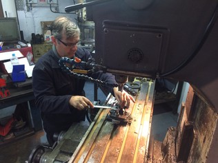
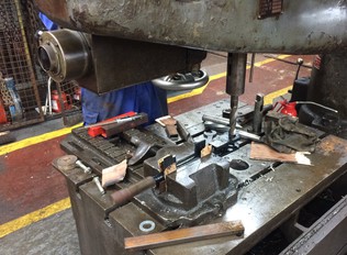
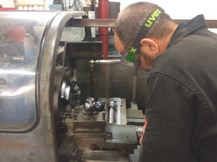
Erle sets up a brake gear equalising link on the Bridgeport mill, ready for boring out the holes to take new bushes. Where the existing holes were worn oval, a milling cutter was a far better tool for this than a drill.
The tender handbrake standard is now completely refurbished and painted, ready for reassembly.
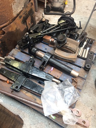
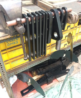
A collection of completed brake components on Saturday. The pile had got a lot bigger by the end of Monday. All of these have been cleaned up, painted, bored out and bushed; some have been made entirely new.
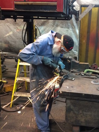
James cleans up the rear cylinder cover. On sunny days we prefer to do dusty jobs outside, where a selection of old wagons can be used as workbenches!
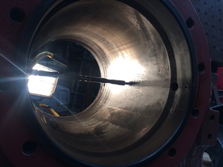
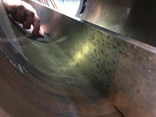
Alan measures the cylinder bores against a parallel. We also measured diameters at many locations along and around the bore, and checked the spacing of the bore from the cylinder mounting face. The bores are generally in very good condition.
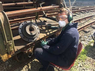
Dave enlarges the holes in the eye of a brake linkage slack adjuster. When the existing holes are round, the radial arm drill does a quicker job than the milling machine, and the hole can be finished with a reamer.
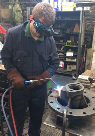
James heats a recalcitrant stud with the oxy-acetylene. These studs attach the slidebar to the cylinder cover, and we will replace them with new. Heating the stud red-hot helps to free it from the tapped hole; it is allowed to cool before we extract it.
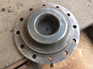
This is one of the front cylinder covers which Erle cleaned up; we're making great progress with the cylinder components.
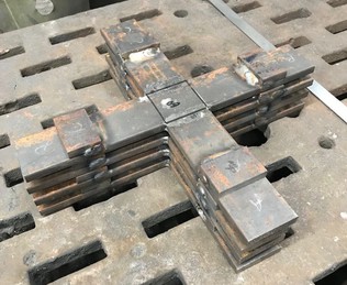
Alan takes the final cut on one of his X-shaped cylinder setup jigs, to make it a perfect fit in the cylinder bore.
Our new volunteer Nick helped Dave manufacture some replacement brake links for the tender. Here he removes scale from the plates ready for painting.
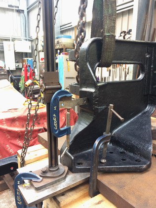
Paul rigged up this arrangement with a height gauge to measure the motion brackets. The hole being measured is where the rear end of the slidebar is attached; it must be aligned with the cylinder centreline when they are attached to the frames.
An array of brake and cylinder components getting a first coat of paint. Four of the brake links are new, while the rest have been refurbished.
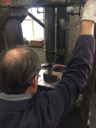
Erle fits plastic bushes into brake link components using the hydraulic press. This was the last task to be completed on much of the brake gear.
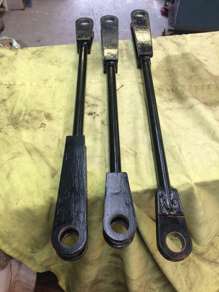
These brake pull rods are all new, replacing worn-out old ones.
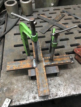
Alan cut and welded his X-shaped jigs from a strip of steel. This was an early stage in the fabrication process.
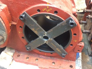
An X-shaped jig trial fitted on one end of a cylinder. These will help us set up the cylinder and slidebar alignment.
The cylinder end bores are slightly different sizes so Alan is making a set of four of these X-shaped jigs.
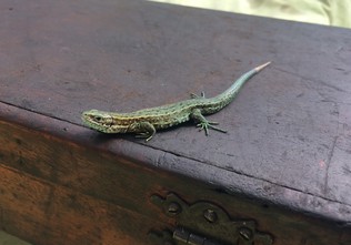
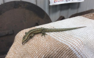
Xiao Long where we first spotted it; sitting on the box of the internal micrometer that we had been using to measure the cylinders.
Xiao Long explores Dave's coat!
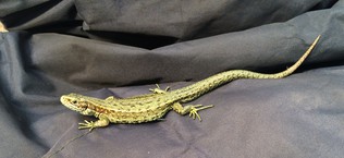
Xiao Long on the loco rear bufferbeam, which is covered with a dust sheet. The smokebox door is visible behind, stored against the shed wall. It's sticking its tongue out!
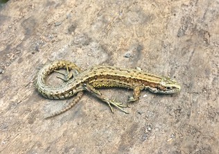
Xiao Long seen on Monday, resting on a track sleeper. We assume it's the same animal we'd seen on the previous days but there could be more than one.
Measuring the alignment of the mounting faces for the cylinders and the motion brackets.
Measuring the cylinder bore diameters with an internal micrometer. Each bore was within a few thou along the length and round the diameter, but the two cylinders aren't the same size as each other at present.